

|
Extron building blocks are a quick configuration tool that can significantly reduce device configuration time. A building block is a collection of processor and gain settings for a particular portion of the signal chain. This allows configuration of an entire mic input, line input, virtual bus return, or line output channel with just two clicks. A comprehensive set of preconfigured building blocks is placed on your computer system when you install DSP Configurator. If you are unfamiliar with DSP processing, the provided building blocks may give you all that you need for complete configuration of your Extron DSP product. The preconfigured building blocks can also be used as a starting point, giving you a basic device setup while staging an installation, then fine-tuning the system during commissioning in the field. Building blocks can be modified, then saved, allowing you to create a customized set of tools unique to your needs. Alternatively, building blocks can be built from a blank screen or an existing configuration, allowing you total flexibility in how you create and deploy this useful and time saving feature. See the Organize Building Blocks section for more information. |
Microphone Building BlocksExtron building blocks for microphones set the gain level for a specific brand name and model, and turn on phantom power if required for that mic. An HP filter is inserted to compensate for common microphone problems such as low frequency noise (thumping) or "plosives" (popping). A bass and treble shelving filter is also inserted into the filter block, with gain level set to 0 dB. This allows adjustment of the microphone tone, if necessary, either via the DSP Configurator software or by programming the gain parameters into a control system and allowing the user to make adjustments. Finally, a compressor is inserted into a dynamics processing block, applying light compression to the channel for the purpose of both normalizing diverse signal levels and protecting the system. Compressor threshold is set at -12 dBFS with Soft Knee added, with a 2:1 compression ratio. The compressor threshold is above target level so as not to affect unity gain (at the target level) through the system. Gain levels used are based on several factors:
The table below shows different mic categories, the reference SPL level at the mic (talker level), mic distance used for that category, and the target channel level. The reference SPL level used accounts for a heightened level produced by a loud talker at 74 dBSPL (based on 65 dBSPL to 68 dBSPL being a normal talking level at 1 meter). A loud talker level was chosen to ensure that all microphone inputs have sufficient headroom. The target channel level is +4 dBu, which allows for sufficient headroom. +4 dBu on the channel displays a meter level of -17 dBFS. Given the max output level of +21 dBu for the device, 0 dBFS is equal to +21 dBu. Therefore a level of -17 dBFS equals +4 dBu (+21 dBu - 17 dB = +4 dBu). When the target level is achieved at the input, maintaining unity gain through the system will produce +4 dBu at the output.
|
![]()
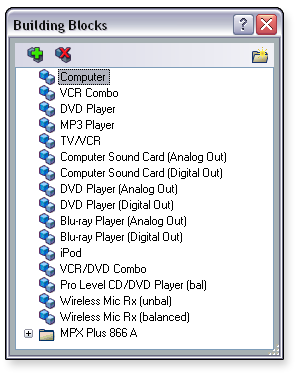
Line Input Building BlocksExtron building blocks for line level devices set the gain level for the specific device and its operating line level. Bass and treble shelving filters are inserted into the filter block, with the gain level set to 0 dB. This allows for tone adjustment, if necessary, either via the DSP Configurator software or by programming the gain parameters into a control system and allowing the user to make adjustments. Light compression is added to the channel to normalize diverse signal levels, with threshold set at -17 dBFS and a 2:1 compression ratio. The compressor threshold is at target level so as not to greatly affect unity gain (at the target level) through the system. The table below shows different line level device categories, and their operating line level. Gain compensation is based on the operating level and the gain required to bring the signal up to the target level. When the target level is achieved at the input, maintaining unity gain through the system will produce +4 dBu at the output. Gain compensation for line levels in dBV is calculated by first converting the source output level to dBu.
|
Virtual Bus Return Input Building BlocksVirtual paths within the DSP are often used to create a submix, which at the same time gives you a single point of control for that submix. Submixes can also be processed as one composite signal, which is different than processing individual channels. The Virtual Return channel building blocks provide a starting point for submix processing and control. Virtual Return Building Blocks cover the following submix scenarios:
For submixing microphones, an HP filter is inserted, as well as bass and treble shelving filters. Light compression is added, which will help to protect both listeners and the system from many microphone channels activating at the same time. Program channel submixes include bass and treble shelving filters, plus light compression. A Loudness filter is also inserted in the path. A program channel submix allows Loudness processing to be added to program material, independent of the microphones. Both microphones and program material can then be routed to the same output. |
![]()
Line Output Building BlocksThe output channel building block inserts an equalization curve into the output signal chain of the DSP. A compressor is inserted on the output, set to a nominal level for speaker protection. The output level is given a nominal setting from which you can make final adjustments to suit the room. The equalization curves used for the output building blocks were generated by measuring the sound power response of an array of nine (9) identical speakers mounted in a large acoustically dead room. For testing, 400 samples were taken throughout the sound field of the speaker array and averaged together, which provided the average sound power response of the nine (9) ceiling speakers. This was repeated with the speaker array at 6 feet, 8 feet, and 12 feet spacings between speakers. The results were merged into a single response curve for all three configurations, comprised of over 1200 samples (total average).
This total average curve was then inverted and loaded into an RTA. Calibrated pink noise was introduced into the Extron DSP and the output of the DSP presented to the RTA. The RTA was put into A - B subtraction mode, with the total average curve being subtracted from the real time pink noise. The resulting response on the RTA was an electrical facsimile of the average acoustic response of the speakers. Parametric filters were then employed on the DSP to flatten the response curve on the RTA. Those filters were then saved into the building block for that speaker type. The purpose of the speaker building blocks is to normalize the inherently non-linear response of a ceiling speaker array, as opposed to flattening the on-axis response of a single speaker. Depending upon the source, additional sweetening of the signal may be desired. For microphones, a high pass filter should be employed to eliminate popping and in certain cases, tone shaping of the speech range may be desired. For music sources, a bass boost is often employed to sweeten the sound at lower levels. Since the "sweetening" for microphones and music sources are, for all intents and purposes, somewhat opposite, adding this to the outputs would render an output ideal for one or the other, but not both. As such, Extron has included the "sweetening" curves into the input building blocks, allowing voice lift and music to coexist in the same speaker system while maintaining attributes needed for both. |
Inserting a Building BlockWhen you select a channel, only building blocks compatible with the selected signal path are displayed in the building blocks list. To insert a building block for an input:
To insert a building block for an output:
After inserting a building block, you can modify the processor blocks if desired (see the other topics in the Workspaces book for more information). |
![]()
Modifying and Adding a Building BlockBuilding blocks can be modified and saved to give you a customized set of tools that are unique to your needs. Any mix-points that are associated with a signal path are not saved and recalled with the associated signal chain building block. You can create a building block from an existing configuration to be used in the future (such as for another input or in another configuration file). To do so:
You can modify a preconfigured building block and save these changes, creating another building block. To do so:
See the Organizing Building Blocks section for information about organizing the listed building blocks. |
Deleting a Building BlockYou can delete a building block from the list in the Building Blocks dialog box. If you delete a default building block, you can restore it if needed (see the Restoring Default Building Blocks subsection of "Organize Building Blocks"). To delete a building block:
- or - To delete an individual building block, right-click the listed building block and select Delete from the drop-down menu. |
![]()
 icon. The Add a Building Block dialog box
opens.
icon. The Add a Building Block dialog box
opens. icon.
icon.